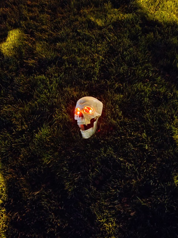
For Halloween I attempted to do a little electronics with my young daughters to make a scary Halloween Skull with Blinking Red Eyes.
Circuit Functions
The circuit is easy to build and consists of 4 parts.
- Photo Diode that triggers the circuit to be activated only at night
- LM555 Timer to blink the Red LEDs for the Skull’s eyes
- Transistors to Drive the diodes
- A +9V Battery for Power
Circuit
Here is the circuit we created. From left to right you can see the Photo Diode, the LM555 in astable mode, and the NPN Transistor powering the two red LEDs.
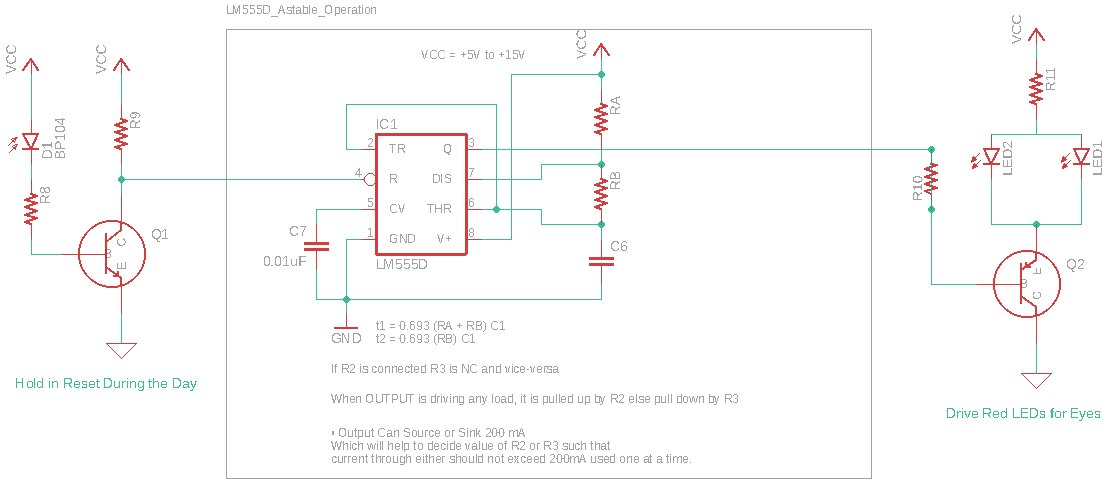
The tricky part for me was to make the Photo Diode circuit trigger when it’s dark - inverse logic. As well as getting the power low so the +9V Battery will last multiple nights. More on that later.
Assembly
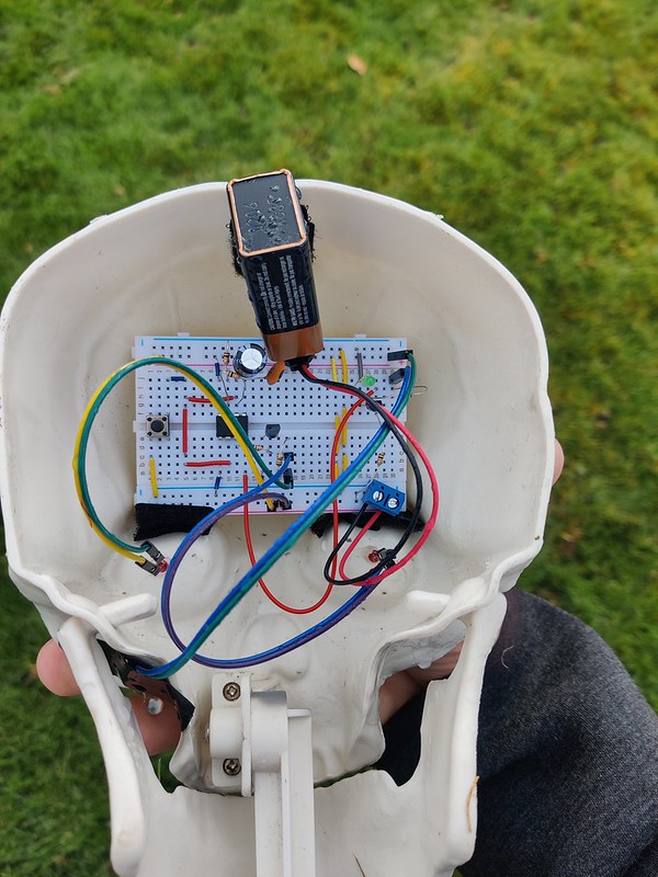
I used Velcro to hold the circuit and battery into the Skull. I drilled holes for the eyes and used hot glue to keep them in. I did a little soldering so the LEDs would stay in. You can see to the lower left - very small - the Photo Diode which needs to face toward the Sun.
Bill of Materials
Here are the values I used. Change the values for RA, RB and C6 for the red LEDs to blink at different times.
| Component | Value | Description |
|---|---|---|
| D1 | Photo Diode | |
| R8 | 10k | Resistor to Base |
| R9 | 10k | Resistor to Collector |
| Q1 | BC547B | NPN BJT |
| LM555D | LM555 | Astable Mode |
| RA | 10k | Adjust to your needs |
| RB | 10k | Adjust to your needs |
| C6 | 1000uF | Adjust to your needs |
| R10 | 10k | Not 100% sure on this |
| LED1 | Standard 20mA LED | |
| LED2 | Standard 20mA LED | |
| R11 | 1.5k | Drives power consumption |
| Q2 | BC547B | Drive to LEDs |
We have the following Duty Cycle for on/off on the LM555 Timer.
\( t_{HIGH} = 0.693 (R_A + R_B) C6 = 0.693 * 20k\Omega * 1000\mu F = 13.86s\)
and
\( t_{LOW} = 0.683 R_B C = 0.693 * 10k\Omega * 1000\mu F = 6.93s \)
where the Duty cycle \( D \) is:
\( D = \frac{R_B}{R_A+2R_B} = \frac{20k\Omega}{30k\Omega} = 66 \% \)
Power
Bare with me this is some RUSTY math!
Since I’m using a +9V battery I estimate it has roughtly 500mAH of juice.
First the current through Q2’s collector for two LED eyes is the +9V battery less the LED drop through the \( 1.5k\Omega \) resistor:
For the LED Driver we have appoximately:
\( I_{B} = \frac{9V-0.7V}{10k \Omega } = 0.83mA \)
\( I_{C} = \frac{9V-0.7V}{1.5k \Omega} = 5.5mA \)
For the Photo Diode in the Daylight we have: \( I_{B} = 2*0.83mA = 1.66mA \)
For the LM555 we can take appoximately 1mA during the night, otherwise it’s in reset. Thus, when the circuit is on it takes.
\( I_{ON} = 0.83+5.5+1 = 7.33mA \)
and when off let’s say it’s just using the power to hold the LM555 in reset for the photo diode:
\( I_{OFF} = 1.66mA \)
So for a 24 hour day we’d have 12 hours using \( 1.66mA \) and 12 hours when the circuit is on. Of those 12 hours only 66% use the full power for about 59mA of power total. The other off time we use 6.6mA total.
\( I_{DAY} = 1.66mA12H(1+0.33) + 7.33mA12H*0.66 = \frac{85mAH}{day} \)
So we can then take:
\( \frac{500mAH}{85maH} = 5.88 Days \)
I’d say this is on the upper range. We’ll see what it really is ….