Raspberry Pi SPI Explained
This post attempts to provide some finer details when using SPI on Raspberry Pi as it pertains to using the Chip Select pins and multiple SPI Interfaces. Note, I will not use MOSI and MISO to ditch the old master/slave nomenclature and use SPO and SPI instead.
Here is a quick diagram which will be explained in the following sections.

The Basics of SPI on the Raspberry Pi
If you use raspi-config you can enable SPI.
raspi-config -> 5 Interfacing Options -> P4 SPI Interface -> Yes (enable)
From here you will see the following two devices created:
$ ls -l /dev/spidev0*
crw-rw---- 1 root spi 153, 0 Apr 19 08:32 /dev/spidev0.0
crw-rw---- 1 root spi 153, 1 Apr 19 08:32 /dev/spidev0.1
We have a single SPI interface which can be accessed 2 ways? What’s the difference between spidev0.0 and spidev0.1? It’s in the Chip Enable pins, also called, Chip Select. Read on!
Wiring for SPI0
Looking at pinout.xyz we see two SPI controllers called SPI0 and SPI1. By default the SPI0 controller is used. For SPI0 we have the following pin assignments. Again SPI and SPO are for Serial Peripheral Input and Output.
Pin 19 / GPIO10 (SPI0 SPO)
Pin 21 / GPIO9  (SPI0 SPI)
Pin 23 / GPIO11 (SPI0 SCLK)
Pin 24 / GPIO8  (SPI0 CE0)
Pin 26 / GPIO7  (SPI0 CE1)
Wiring up SCLK, SPO, and SPI is easy but what about CE0 and CE1? This is the relationship:
/dev/spidev0.0 drives CE0 Low
/dev/spidev0.1 drives CE1 Low
Thus, from spidev0 we can control 2 SPI Chips by opening files for /dev/spidev0.0 and /dev/spidev0.1. You don’t have to use the CE pins, you can use GPIO instead, but it’s more work in software as it won’t automatically happen. As you’ll see soon the SPI1 allows for 3 CE pins.
What about SPI1-SPI6?
We can enable many more SPI Controllers, it appears to be 7 for a standard Raspberry Pi. Let’s add the 2nd SPI Bus - SPI1 by editing the file /boot/config.txt as the root user. Here, we have to add a device tree overlay.
[all]
dtoverlay=spi1-3cs
Multiple overlays can be defined, but I’m not going into that. Here is a good doc: device tree overlay on the Raspberry Pi. This doc shows 7 total SPI Controllers can be added with overlays. I haven’t looked at all the restrictions with the overlays so saying 7 total SPI controllers may not be possible. Here is some info on the SPI Hardware.
Syntax for an SPI Overlay
For the overlays we have the following syntax:
spi{m}-{n}cs
Where m represents the SPI bus or controller, and n is the number of CE chip-enable pins to use. For example, if we overlayed spi1-3cs after rebooting we’d have:
$ ls -l /dev/spidev0*
crw-rw---- 1 root spi 153, 0 Apr 20 21:17 /dev/spidev1.0
crw-rw---- 1 root spi 153, 1 Apr 20 21:17 /dev/spidev1.1
crw-rw---- 1 root spi 153, 2 Apr 20 21:17 /dev/spidev1.2
It makes sense to specify the number of pins needed for chip enables as you may only have one device and need the pins for other purposes.
From the overlay we can also set other SPI bus parameters such as speed. See the device tree overlay.
SPI in C and the Unix Kernel
To conduct a transfer we need to combine a struct spi_ioc_transfer with a file descriptor we get from opening /dev/spidev0.0 for example.
No matter what language, API, library, framework or tool you’re using it’s probably using the Kernel’s struct spi_ioc_transfer. This structure configures the buffers of tx and rx data, the SPI clock speed and some other parameters. It can be found in /usr/include/linux/spi/spidev.h.
Pseudo Code to Make a Transfer
- open a file descriptor
fd0for/dev/spidev0.0 - create a
struct spi_ioc_transferforfd0 - Use the SPI bus using both the
fd0and thespi_ioc_transferstructure to do an SPI transfer
Step 3 looks like the code below. See how we combine the file descriptor that relates to say /dev/spidev0.0 and an spi_ioc_transfer for the ioctl function. It’s not necessarily a 1-to-1 mapping.
ioctl(fd0, SPI_IOC_MESSAGE(1), &spi_ioc_transfer);There are many combinations possible when using file descriptors and spi_ioc_transfer structures depending on the use case. Above, we used a simple 1-to-1 mapping.
Detailed Settings of the SPI Bus
In user space we initialize the spi_ioc_transfer structure. Note, this does not correspond to any /dev/spidev0.0 or any file for the specific SPI device. It is mapped separately, see above.
#include <linux/spi/spidev.h

struct spi_ioc_transfer transfer;

transfer.tx_buf = (unsigned long) NULL; // the buffer for sending data
transfer.rx_buf = (unsigned long) NULL; // the buffer for receiving data
transfer.len = 0;                       // the length of buffer
transfer.speed_hz = speed_hz;           // SPI clock speed
transfer.bits_per_word = bits_per_word; // bits per word
transfer.delay_usecs = 0;               // delay in us
transfer.cs_change = cs_low;            // before xfer will go high but will remain low after
transfer.tx_nbits = 0;                  // no. bits for writing (default 0)
transfer.rx_nbits = 0;                  // no. bits for reading (default 0)
transfer.pad = 0;                       // interbyte delay - check version
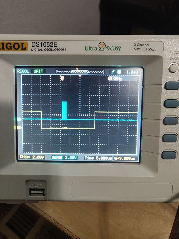
The transfer.cs_change field confused me at first. If we leave this at 0 or false you’d get what you’d expect and the SPI Controller will drive CS low only when a transfer is in place. If we set to 1 or true the SPI controller will just leave CS low for the most part and not change it. I use the words “most part” here as it will toggle for some time before the transfer even happens, but after it will be kept low. This is in the oscilloscope pictures below.
Oscilloscope Captures
The blue/teal/turquoise color is SCLK and the yellow color is the CS Pin. These captures are taken after tweaking different spi_ioc_transfer fields.
When transfer.cs_change=1
When does CS go high again? I’m not actually sure my time scale wasn’t long enough.
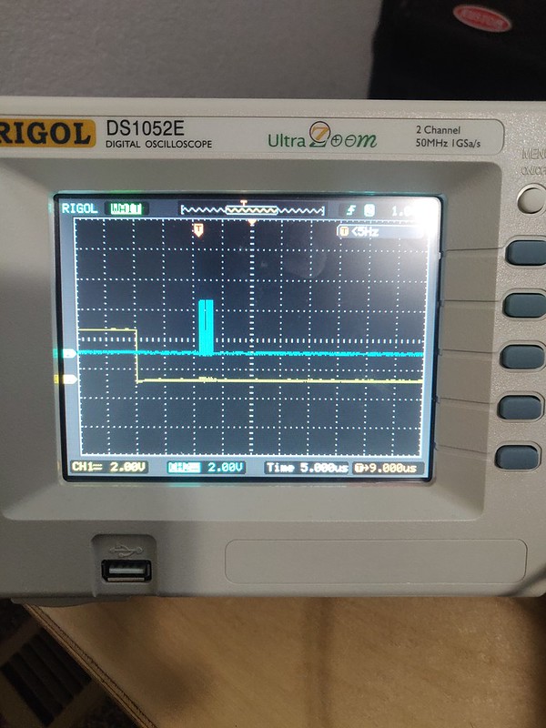
When transfer.cs_change=0
My guess is this is normally what you’d want.
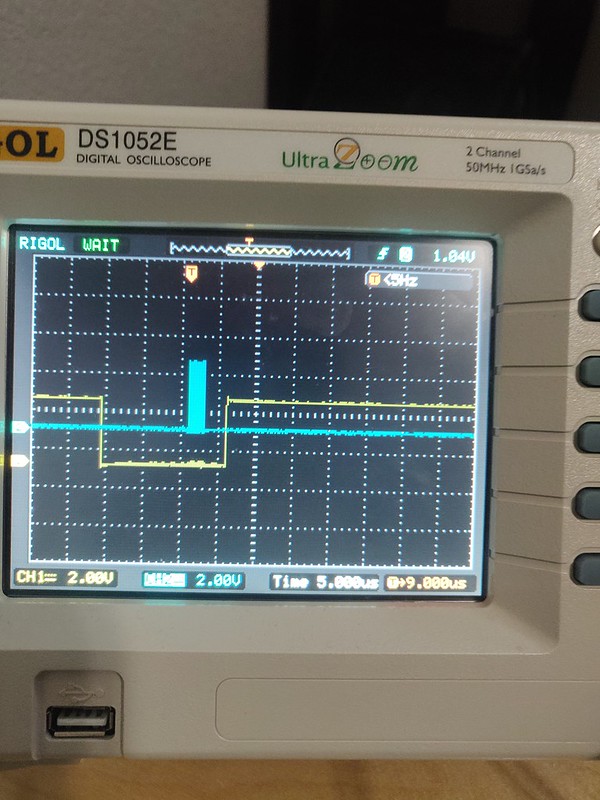
With and without the transfer.delay_usecs
Here is a normal transfer where transfer.delay_usecs=0 and transfer.cs_change=0.
When transfer.delay_usecs=10
I’m not 100% sure it was set to 10! Sorry. Also, if you set it to high I noticed it would ignore it. There must be an upper limit. We also must have transfer.cs_change=0.