LSM9DS1 Command Line Tool for Raspberry Pi
I recently created a LSM9DS1 Command Line Tool for the Raspberry Pi. This tool was used to capture Accelerometer and Gyroscope data. I did an experiment to see what the readings look like, how the sensor behaves and the noise levels. This experiment is far from perfect but gives good insight and understanding.
Sensor Setup
The LSM9DS1 was taped to the tread of a \( 16" \)stroller tire. The location was directly on top of the tread so the wheel had to be spun up in the air. The wheel was parallel to the ground as the stroller was on it’s side. The axis of the Accelerometer had Z facing outward, X facing along the rotation of the wheel, and Y facing perpendicular to the rotation of the wheel.

Accelerometer on Wheel
The wheel was close to parallel with the floor, but not perfect. Thus, Accelerometor data won’t read \( 1g \) for the Y-Axis and \( 0g \) for the X and Z Axes as an ideal measurement would. Also, the wheel itself is not very true. From this we should see some Gyroscope rotation as the tire moves.
The Experiment
For the experiment the LSM9DS1 was first at rest. The wheel was spun \( 4 \) times counter-clockwise, then stopped, then spun around once clockwise, then put back to rest. The total experiment took about \( 17 \) seconds.
For the LSM9DS1 there was no calibration and the readings were raw. We have the low-pass and high-pass filters turned on for the Gyroscope. ODR was at \( 14.9 \) Hz. The lowest bandwidth settings were used.
Analysis of Accelerometer Readings
The goal here is to first convert the raw readings from LSM9DS1 Accelerometer into units of \( g = 9.80665 \frac{m}{s^2} \).
Let’s first note that the Accelerometer and Gyroscope has raw values from \( -32,768 \) to \( 32,767 \) since it’s a 16-bit 2’s compliment value. The datasheet specifies that the Linear Acceleration sensitivity is \( 0.061 \) for a \( \pm 2g \) setting. Thus, we can use the following equation to convert the raw readings into \( g \).
First notice this convenience:
$$ 0.061 \times 10^{-3} \approx \frac{2}{32768} = \frac{1}{16834} = 2^{-14} $$
Which allows us to convert from raw to \( g \) like so:
$$ v_g = \frac{t}{16384} $$
Here \( v_g \) is the value from the Accelerometer in \( g \) and \( t \) is the raw 16-bit reading.
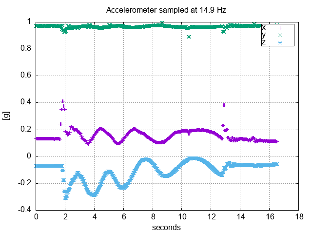
Accelerometer Readings from a Rotating Wheel
We observe that the Y-Axis is about \( 1g \) the entire time. This makes sense. The X and Z Axes, however, have some real DC bias. Calibration would have to be done to take them out. Also, notice when the wheel spins from rest there is a high-frequency component. This experiment would warrant both the X and Z Axes would be at \( 0g \) if ideal. If we take the DC bias out they go up and down by about \( 0.1g \). It’s hard to say if this change of \( 0.1g \) is too much or too little. Again the wheel was not parallel with the floor and the it’s not true, both contributing factors to the X and Z Axes changing.
Analysis of Gyroscope Readings
The Gyroscope measures degrees per second or \( \frac{^\circ}{s} \) in 3-Axes. If we had a reading of \( 360 \) we’d be going in a complete circle each second.
From the datasheet we can see that we have \( 8.75 \frac{mdps}{LSB} \) where \( mdps \) is milli-degrees per second. Thus, to convert a raw reading from the Gyroscope we can do:
$$ r_d = 0.00875t $$
Where \( r_d \) is the Gyroscope reading in degrees per second and \( t \) is the raw reading.
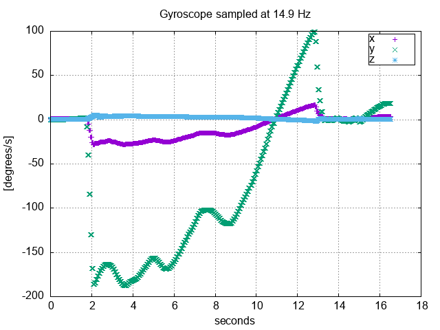
Gyroscope Readings from Rotating Wheel
From the graph we can see that most the action is on the Y-Axis. Imagine yourself on the edge of a rotating wheel. You’d be spinning along the Y-Axis. This is why most people probably get dizzy on a Merry-Go-Round. Here the sign of the spin is clockwise or counter-clockwise. The wheel was spinning counter-clockwise first, hence a negative reading, then the last rotation is clockwise for a positive reading. Again the High-Pass filter was enabled and we see no DC-Bias on any of the Axes. A rotation reading of \( 180 \) would represent a full rotation every \( 2 \) seconds. I can read 4 rotations out of it, the 5th the other direction becomes a little more challenging.
Now, for the X-axis. This represents spinning around the wheel along the Axis of rotation. We see this number flip when the rotation direction changes. This reading is much less than what we see in the Y-Axis.
The Z-Axis is to be expected with no rotation.
Where to go from Here?
I hope you enjoyed this post and please leave comments below!